Guaranteed Sites Plans in Under 24 Hours

US housing authorities issue millions of building permits each year, which can make building a home sound deceptively simple. But getting that permit often comes with a major requirement: a complete architectural drawing plan. This isn't just a suggestion; it's the official playbook for your entire project. These detailed drawings are what stand between your vision and costly construction mistakes. They ensure everyone involved speaks the same language, helping you get your permit and bring your dream home to life, one correct detail at a time.
But they have good reasons to do so. Architectural drawings are your best tools for laying out your home and planning your renovation project.
In this post, we’ll take a look at the three main categories of architectural drawings and what you can expect to see when looking at plan drawings, section drawings, elevation drawings, and more.
Table of content
What are architectural drawings? 3 main categories of architectural drawings Plan drawings Roof plans Reflected ceiling plans Site plans Plan callouts Plan details Section drawings Full sections Half sections Offset sections Removed sections Revolved sections Elevation drawings Get architectural drawings like site plans quickly and easily FAQs
What are architectural drawings?
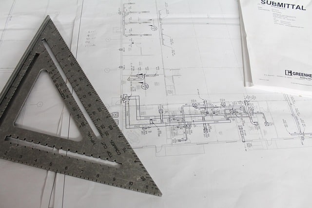
As the name suggests, architectural drawings are drawings of a building's architectural details. Traditionally, these are done in ink on paper, but modern technology has made digital architectural drawings common. These drawings use pre-set conventions, including units of measure, different scales, annotations, and cross-references.
Architectural drawings can be incredibly useful for designing buildings and houses, planning out renovation projects, and helping during the construction process.
Why Architectural Drawings are Essential
Think of architectural drawings as the script for your construction project. They’re not just a formality for the permit office; they are the foundational documents that guide every decision, from the first shovel in the ground to the final coat of paint. Without them, you’re essentially asking your entire team—from contractors to electricians—to improvise. A clear set of drawings ensures that everyone is working from the same playbook, which is the best way to keep your project on schedule and within budget. They transform an abstract idea into a concrete, actionable plan that everyone can understand and follow.
Communication and Permit Applications
Architectural drawings are the universal language of construction. They help everyone involved, from you to your builder, understand the project's scope and details. These documents provide clear instructions that ensure your project is built correctly and safely. This is especially critical when it comes to permit applications. Your local building department needs to see a detailed, professional drawing, like a site plan, to verify that your project complies with zoning regulations and building codes. Submitting a clear and accurate plan is the fastest way to get your permit approved and avoid frustrating delays that can stall your project before it even begins.
Qualities of a Good Architectural Drawing
Not all drawings are created equal. A successful architectural drawing is like a detailed map that shows exactly how a building will look and be put together. To be effective, it must be accurate, clear, easy to read, and detailed. This means using standard symbols, precise measurements, and comprehensive notes that leave no room for interpretation. It also needs to be client-friendly, so you can easily understand what you’re looking at. When you work with experienced drafters, you get plans that meet these high standards, which is why we can offer a guaranteed acceptance by your building department. A quality drawing is your best insurance against misunderstandings and construction errors.
3 main categories of architectural drawings
The three main categories of architectural drawings are plan drawings, section drawings, and elevation drawings. Let’s take a look at the different types of drawings you’ll see within each of these categories.
Plan drawings
Plan drawings give a bird's-eye view of a property. They illustrate the features inside a building, letting the viewer know where rooms and furniture will go inside. They also provide information on the size of each room, though most people do not draw plan drawings in perspective.
Here are some of the different types of plan drawings you might come across.
Floor plans
A floor plan is the most common type of plan drawing. Think of it as a map of a single level of a building, viewed from directly above. It’s as if you sliced the building horizontally about four feet off the ground and removed the top half. This unique perspective allows you to see the complete layout of the space, including where the walls, doors, and windows are located. It’s an essential tool for understanding the flow between rooms and planning how to arrange furniture. While floor plans show the dimensions and layout of each room, they are typically drawn to scale but not in perspective, keeping the focus purely on the spatial arrangement.
Roof plans
A roof plan is an architectural drawing that gives you a top-down perspective of a building’s roof. Roof plans are essential and help ensure your roof is built correctly and works with the rest of your building’s structure.
Some major components of roof plans are:
Roofline: The roof plan will display the roof's overall shape, including any overhangs or eaves.
Slope and pitch: The roof’s slope and pitch are usually displayed with arrows showing the slope's direction and how steep the incline is.
Materials: A roof plan will list the roofing materials used in the roof construction, like shingles or tiles.
Openings: If your roof includes any skylights, chimneys, or vents, those will be displayed on the roof plan.
Structural elements: A roof plan must include the location of any rafters, trusses, or beams that support the roof.
Drainage: You’ll see the location of any gutters, downspouts, and drainage systems that will help manage water runoff on your roof.
Reflected ceiling plans
A reflected ceiling plan (RCP) is a type of architectural drawing that shows all the features on a room's ceiling as if the ceiling were reflected onto the floor. They’re mainly used in construction and interior design.
RCPs display the placement of:
Lighting: This includes things like light fixtures, ceiling lights, recessed lights, and chandeliers.
Ceiling layout: If your ceiling has tiles or panels, the RCP will show how they should be laid out.
HVAC: The RCP will display locations of heating and cooling system components like vents, air returns, and air conditioning systems.
Electrical elements: Any ceiling-mounted electrical components, such as speakers or smoke detectors, will be displayed on reflected ceiling plans.
Site plans
A site plan is an architectural drawing that shows the entire construction site, including the surrounding landscape, utilities, and roads. Some people draw site plans above the building as though they are showing a roof plan. Others make drawings like first-floor plans, showing how the exterior affects the interior.
Site plans can include the following elements:
Property boundaries: Your site plan will include the outline of the property, including its dimensions.
Buildings and structures: You’ll see any buildings and structures on your property.
Landscaping: The site plan may include details of landscaping elements like trees, gardens, or lawns.
Utilities: A site plan will clearly identify the location of any utility lines for water, sewer, gas, or electricity. This will help workers dig safely during construction.
Access points: This includes any driveways, walkways, or entrances to your property.
Scale: Your site plan should clearly identify the scale of the drawing.
Learn more about different types of site plans here: Which Site Plan Is Best for You?
Landscape drawings
While a site plan gives you the big picture of your property, a landscape drawing zooms in on the details of your outdoor spaces. Landscape architectural drawings are similar to site plans but focus on outdoor elements like plants, patios, and walkways. These plans map out everything from the specific types of trees and shrubs you’ll plant to the materials for your new deck or the path of a garden walkway. They can also include plans for irrigation systems and outdoor lighting, ensuring your exterior is both beautiful and functional. Think of it as the detailed blueprint for your property’s curb appeal and outdoor living areas.
Finishing drawings
Once the structure is up, it’s the small details that turn a house into a home. That’s where finishing drawings come in. Finishing drawings show details about materials like flooring, paint colors, and trim. This type of plan acts as a guide for all the aesthetic choices in your project. It specifies everything from the pattern of the bathroom tile and the style of the kitchen cabinets to the exact paint codes for each room. For contractors and designers, these drawings are essential for ensuring the final product matches the homeowner’s vision precisely, leaving no room for guesswork on the final touches.
Electrical drawings
Functionality and safety are paramount in any build, which is why electrical drawings are so critical. Electrical drawings show where all the wiring, lights, outlets, and switches will go. This isn't just about picking a spot for a lamp; these plans detail the entire electrical system, including circuit paths, junction box locations, and the placement of specialized outlets for appliances. A clear electrical plan helps electricians install everything correctly, ensures the building passes inspection, and makes sure your home is powered safely and efficiently for years to come.
Excavation drawings
Before you can build up, you have to dig down. Excavation drawings provide the necessary instructions for all groundwork. These plans show details about digging, trenches, and how the ground will be shaped for the foundation. They guide the construction crew on how deep to excavate, where to create trenches for utilities like water and sewer lines, and how to grade the land to prevent future drainage issues. Paired with a comprehensive site plan, an excavation drawing ensures your project starts on a solid, stable, and properly prepared foundation.
Plan callouts
A plan callout gives you a detailed view of a specific area of an architectural drawing. Plan callouts are great for conveying information about smaller details in a plan to reduce the risk of mistakes during construction.
The main components of plan callouts are:
The highlighted area: A portion of the main drawing is “pulled out,” often a circle, rectangle, or cloud shape, to indicate the area is being enlarged.
Detailed views: These are more detailed drawings of the highlighted area with more specific information, dimensions, notes, and annotations.
Additional information: This includes detailed information about construction methods, materials, finishes, or any other information crucial for constructing the things in the callout.
Plan drawings often have a quarter-inch scale, where one-quarter inch of a line represents one foot of the property. A plan callout has a larger scale, usually a half-inch scale, making details easier to see.
Plan details
Plan details are also known as detail drawings or construction details. They are highly detailed illustrations that give in-depth information about the assembly, materials, dimensions, and construction methods for specific parts of a building.
Detail drawings include:
Components: These show the individual components of an assembly and how they fit together.
Dimensions: Plan details will include measurements and dimensions to guide construction.
Annotations: Notes, labels, and other annotations help explain materials, construction techniques, and any other special instructions.
Cross-sections: Plan details often include cross-sectional views of assemblies to help you understand how they work.
Materials and finishes: This will include any details about the wood, metal, concrete, and other materials used for construction.
Construction methods: These are instructions about assembling or installing components, including the order of the construction steps and the tools and equipment you will need.
Section drawings
As the name suggests, section drawings illustrate sections or parts of buildings. Section views look at structures as though they have been cut along an imaginary plane, letting you see internal features that aren’t visible in standard plan drawings.
Section views are essential for architects, engineers, and builders. They communicate complex information about a project's design and construction.
Here are some of the types of section drawings you might see.
Full sections
A full section drawing, also known as a section drawing, is an architectural drawing that shows a vertical cut through the entire length or width of a building or structure. This cut provides a view of the internal components, construction details, and relationships between different parts of the structure.
Half sections
Half-section drawings only reveal half of the internal components of a structure while also displaying the exterior. In construction, half-section drawings will show the outside walls of a building and what’s on the other side of those walls. They help you understand how internal and external elements of the construction relate to each other.
Offset sections
Offset sectional drawings show features that are not in a straight line but need to be displayed in a single-section view. The “cutting plane” line in an offset section drawing is bent or offset to pass through these features. This gives you a comprehensive view of the important internal components.
Removed sections
A removed section, sometimes called an exploded section, pulls out a part of the drawing to view in greater detail, separate from the main drawing. This helps you look at some aspects in more detail without disrupting the rest of the architectural drawing.
Revolved sections
Revolved sections show small sections of an object or room. The artist draws the element as if they are rotating it 90 degrees, helping you see it better. This can help you see what problems could occur if the object shifts, which can be helpful for maintenance and future repairs.
Learn more about section drawings in our post about six types of section views.
Elevation drawings

Elevation drawings are architectural drawings that display the exterior views of a building from different sides. Elevation drawings help you understand the appearance, proportions, and design details of a building’s facades.
The main elements of elevation drawings include:
Exterior views: show the arrangement of doors, windows, materials, and other facade elements.
Architectural features: Elevation drawings detail the placement and style of doors and windows, materials used for cladding a building, and architectural details like moldings and trims.
Dimensions and scale: An elevation drawing will include the dimensions of a building and the scale of the drawing.
Most drawings show the sides of structures at a 1:100 scale, though you can find elevations with other scales.
You may also find elevation drawings of the inside of specific rooms like kitchens. They can help you visualize things like the location of cabinets and appliances to help with design and installation. Elevation drawings can be very helpful for renovations and interior design of spaces like offices, and you can use them alongside site plans.
Elevation callouts and details
Similar to plan callouts, elevation callouts and details provide a magnified look at specific areas of a building's exterior. These are especially useful for showing intricate features that aren't clear on the main elevation drawing. Think of them as a close-up shot that focuses on the construction of a particular element, like a window frame, a decorative trim, or the pattern of stone veneer.
These detailed drawings include precise dimensions, specify materials and finishes, and can even show how different components should be assembled. They are critical for ensuring that the aesthetic details of the building are executed correctly, helping contractors visualize the final product and avoid mistakes on features that define the building's character.
As-built drawings
While the previous drawings are all about planning, as-built drawings are a record of what was *actually* constructed. During a project, changes are often made on-site due to unforeseen conditions or client requests. As-built drawings are the original design plans, marked up to reflect these modifications, creating a final, accurate picture of the completed building.
These drawings are incredibly valuable for property owners. They serve as a definitive record of the building's structure, including the exact locations of pipes, wiring, and structural changes. If you ever plan a future renovation or need to perform maintenance, as-built drawings provide a reliable map of your property, preventing costly and dangerous guesswork down the road.
Understanding Key Drawing Concepts
Now that you’re familiar with the main categories of architectural drawings, let’s touch on a few core concepts that will help you make sense of them. Understanding how these drawings are created and the different styles they come in will make it much easier to read your plans and communicate with your contractor or designer. These are the foundational ideas that bring a project from a simple idea to a buildable reality, ensuring everyone is on the same page.
Orthographic projection
Most of the architectural drawings you’ll use for a permit, like a site plan or floor plan, are "orthographic." This is a technical term for a simple idea: the drawing is presented as a flat, two-dimensional view without any perspective. Unlike a photograph where objects in the distance appear smaller, an orthographic drawing shows everything at the same scale. This method is essential for construction because it allows for precise, consistent measurements. Every line on the page corresponds to a real-world dimension, which is critical for builders to follow the plan correctly and for permit offices to approve your project.
Common drawing styles
Beyond the main categories, you’ll also hear different terms that describe the style or purpose of a drawing. These styles serve different functions throughout the design and construction process, from initial brainstorming to the final build. Knowing the difference can help you understand what kind of information you’re looking at and what it’s meant to be used for. Here are a few of the most common styles you’re likely to come across when working on a home or commercial project.
Architectural sketches
Think of architectural sketches as the first draft of an idea. These are often quick, hand-drawn concepts that architects and designers use in the early stages of a project to explore different layouts and designs. They are fantastic for brainstorming and visualizing possibilities without getting bogged down in technical details. While they are a crucial part of the creative process, sketches are not used for construction or permits because they lack the precise measurements and detailed information required for building.
Blueprints
You’ve probably heard the term "blueprints" used to describe any architectural plan, but its meaning has evolved. The name comes from an old printing process that produced white lines on blue paper. Today, that method is obsolete. The modern equivalent is typically a digital file (like a PDF) printed in black and white, more accurately called "construction drawings" or "architectural plans." These are the official, detailed documents that contain all the necessary information—from dimensions to materials—that contractors use to build the project and that you submit for your permit.
3D renderings
If orthographic drawings are the technical guide, 3D renderings are the visual preview. These are highly realistic, computer-generated images that show what your finished project will look like from any angle. They are incredibly helpful because they can illustrate textures, lighting, and colors, giving you a true feel for the space before construction even begins. While they are an amazing tool for visualization and making design decisions, they are not used for the actual build, as they don’t contain the precise, to-scale measurements found in construction drawings.
How to Read an Architectural Plan
Architectural drawings can look like a complex puzzle of lines and symbols, but they're actually pretty straightforward once you know what to look for. Understanding the basics will help you visualize your project, communicate effectively with your contractor, and ensure everything is on the right track. Think of it as learning the basic grammar of your project's language. Let's break down the key elements you'll find on almost any professional plan.
The title block
Think of the title block as the drawing's ID card. You'll usually find it in the bottom right-hand corner of the page, and it contains all the essential administrative details for the project. This is where you'll see the project name and address, the drawing number (especially important in a set of multiple pages), the date the drawing was created, and any revision dates. It also includes the name of the firm or drafter who created the plan. When you get a site plan for a permit, the title block is one of the first things an official will check to verify the project's details.
The scale
The scale is what translates the drawing on the page into real-world dimensions. It tells you how much the drawing has been reduced in size compared to the actual building or site. For example, a common scale is 1/4" = 1'-0", which means every quarter-inch on the paper represents one foot in reality. Always check the scale before you start taking any measurements from the plan. It’s usually listed in the title block or noted directly on the drawing. Understanding the scale of your site plan is fundamental to grasping the actual size and scope of your project.
The north arrow
Somewhere on your plan, you'll find a north arrow. This simple symbol, which looks like a compass, is incredibly important because it orients the drawing to the real world. It shows you which direction is north, which helps you understand how the building is situated on the property. This orientation affects everything from where the sun will hit your windows in the morning to the placement of your garden or patio. For contractors, it's a critical reference point for laying out the foundation and other site elements correctly. It’s a small detail that provides a huge amount of context.
Decoding symbols and the legend
Architectural plans use a standardized set of symbols to represent different building components. Thick, solid lines often indicate exterior walls, while thinner lines represent interior walls. An arc shows which way a door swings open, and dashed lines might represent overhead features like cabinets or beams. You don't have to memorize them all. A good set of drawings will include a legend or key that acts as a dictionary, defining what each symbol means. Always refer to the legend to avoid any confusion about what you're looking at. It’s your guide to interpreting the drawing's language accurately.
Can You Draw Your Own Plans for a Permit?
It’s a question many homeowners and contractors ask: can I just draw my own plans to get a building permit? The idea of saving time and money by handling it yourself is definitely appealing, especially when a project budget is tight. For very simple projects, like a small fence or a basic shed in some jurisdictions, a hand-drawn sketch might be all you need. However, for most construction, additions, or significant landscaping projects, the reality is far more complex. Local building authorities have specific and often strict requirements for what they’ll accept, and these aren't just suggestions—they're rules designed to ensure safety and compliance with local zoning laws. Before you invest hours into drawing your own plans, it's important to understand the potential challenges. Going the DIY route can sometimes lead to more delays and expenses than you were trying to avoid. A professionally drafted plan is often the most reliable and efficient path to getting your permit approved without a hitch, letting you move forward with your project confidently.
The Risks of DIY Plans
The first and biggest hurdle you'll face is local regulations. Every county and city has its own set of rules, and many explicitly require plans to be prepared by a design professional. As one homeowner discovered, their county demanded architect-stamped drawings even for a building they were told was allowed. These rules are in place to ensure every project meets critical safety and zoning standards. Trying to create a plan without a deep understanding of your local building code can lead to an immediate rejection, sending you right back to square one. It’s always best to check your local building department’s website first.
Beyond just meeting regulations, your plans need to be clear and correct. Architectural drawings are a communication tool, translating your vision into a technical guide for the permit office and your build team. A DIY plan might seem clear to you, but small errors in scale, missing property line information, or unclear labels can cause major confusion. These mistakes not only delay the permitting process but can also lead to expensive corrections once construction is underway. Getting the details right from the start is essential for a successful project, which is why so many people rely on permit-ready site plans to avoid these headaches.
There are other risks to consider, too. If you’re pulling inspiration from existing plans you found online, you could run into copyright issues if you use them without permission. More importantly, creating a comprehensive plan is more than just drawing the outline of a building. You need to include details like the location of utility lines, easements, topography, and existing structures. Forgetting a key element is an easy mistake to make, but it can bring your project to a halt. A professional plan ensures all necessary components are included, giving you a complete picture of your property and project.
Get architectural drawings like site plans quickly and easily
Now that you know how useful and informative different types of architectural drawings are for the construction process. If you need help putting together architectural drawings for your project, My Site Plan can help. We can help you create a simple or detailed site plan to help you prepare for your project or submit for permits. Ready to get started? Take a look at our site plan options!
FAQs
Which architectural drawings show the side view of a building?
Elevation drawings show a building's side view. They usually show the exterior sides of a house or building and include details like architectural features, the placement and style of doors and windows, and information about building materials or wall cladding.
Elevation drawings are beneficial during renovations as they provide a precise view of the building’s exterior or a specific interior wall.
Can I do my own architectural drawings?
You can technically create your own architectural drawings, but if you need drawings to obtain a building permit, it might be a better idea to let a professional create them. This will ensure that your drawings accurately represent your building project and include all the necessary details to help your permit get approved.
What is the purpose of using different scales in plan drawings?
In plan drawings, different scales are used to show varying levels of detail. Smaller scales provide an overall view, while larger scales highlight specific areas like kitchens or bathrooms, making details clearer for planning and construction purposes.
How do reflected ceiling plans (RCPs) aid in home design?
Reflected ceiling plans (RCPs) are essential for visualizing the placement of lighting fixtures and understanding ceiling heights throughout a home. They help architects and designers plan the lighting layout and any ceiling modifications needed to accommodate fixtures or architectural features.
Why might someone choose an offset section drawing over a full section drawing?
Offset section drawings are chosen when the architectural features of a room are not aligned along a straight plane, such as in L-shaped or oval rooms. They provide a more accurate visualization of different parts of the space, which can be crucial for effective design and planning.
How do broken-out and revolved section drawings improve understanding of a building’s layout?
Broken-out and revolved section drawings allow for a detailed view of small, specific parts of a building or room. These drawings are particularly useful during renovations or repairs as they show how components fit together and reveal potential issues with the structure's current layout or design.
This post was originally published by Ryan Crownholm on June 5, 2023. It was updated on July 29, 2024, to reflect the latest information.
About the author

Ryan Crownholm
Ryan is a construction technology founder and former contractor with 15 years of hands on experience in residential and commercial construction. He has been creating site plans for more than 25 years, supporting tens of thousands of homeowners and contractors across the United States. As the founder of MySitePlan.com, his work is grounded in real world permitting requirements, plan review feedback, and practical compliance standards used by local building departments.
Key Takeaways
- Architectural drawings align your entire team: These plans act as the single source of truth for your project. They provide clear, technical instructions that ensure you, your contractor, and the permit office are all working toward the same goal, which helps prevent expensive errors.
- Different drawings offer unique perspectives: The three main types each serve a specific purpose. Plan drawings show a top-down view of the layout, elevation drawings display the building's exterior from each side, and section drawings reveal a cut-through view to show construction details.
- A professional plan is key for permit approval: While it can be tempting to draw your own plans, most building departments have strict requirements. Using a professional service for documents like site plans ensures all necessary details are included, giving you the best chance for a smooth and successful permit application.
